CLASS V FOIL — LOWER FIRST BICUSPID
Class V cavity prepared in
lower first bucuspid, buccal
surface, for the reception of gold foil as the restorative material.
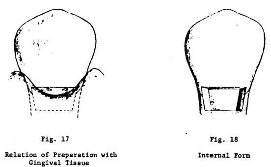
OUTLINE FORM
(Figs. 17 & 18)
1. Occlusal
Outline
a.
Flat and straight.
b.
Placed in a self cleansing area
c. Parallel with occlusal
plane of the teeth.
d.
Sufficiently long so that the mesio-occlusal and disto-occlusal line angles are covered by the gingival
tissue.
2. Gingival Outline
a.
Placed beneath the level of the gingival tissue.
b. Parallel
with occlusal outline.
c. Flat
and straight.
3. Mesial
and Distal Outlines
a.
Straight, connecting occlusal and gingival outlines.
b.
Parallel to the respective general contour of the tooth.
c.
Include a portion of the mesiobuccal and disto-buccal line angles of the tooth sufficiently to be
covered by the gingival tissue when restoration is completed.
4. This presents the typical
Class V outline form for a gold foil restoration. There are numerous atypical
outline forms for which the typical outline serves as a basis.
This cavity form was refined
from the Black type of cavity by W.I. Ferrier.
CLASS V FOIL - OUTLINE FORM,
LOWER FIRST BICUSPID
RESISTANCE AND RETENTION FORM
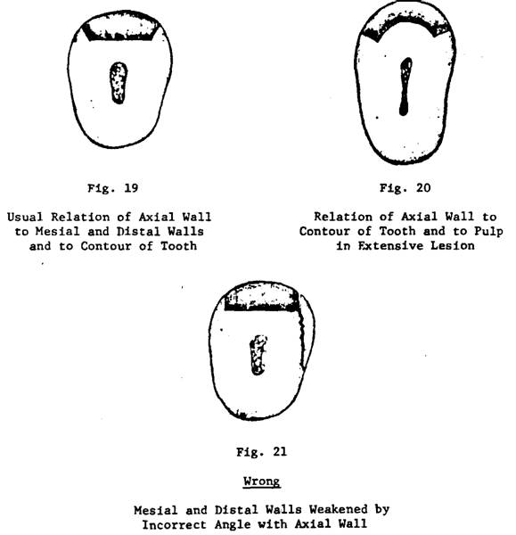
1. Axial Wall (Figs. 18, 19,
20) -
a.
Must be smooth and at uniform depth.
b. Established
just within the dentin. Should parallel the surface contour
of the tooth rather than the long axis, occluso-gingivally
(Fig. 23).
c.
Usually flat. If the tooth is highly contoured, or if the cavity is extensive mesio-distally, the axial wall follows the contour of the
tooth surface, mesio-distally (Fig. 20).
2. Mesial
and Distal Walls (Figs. 18, 19, 20)
a.
Flat and straight.
b.
Form an obtuse angle with the axial wall and thus slope outward from the axial
wall.
c. They
are definitely never undercut or even at right angles to the axial wall (Fig.
21).
d.
Meet occlusal and gingival walls in sharp definite
line angles.
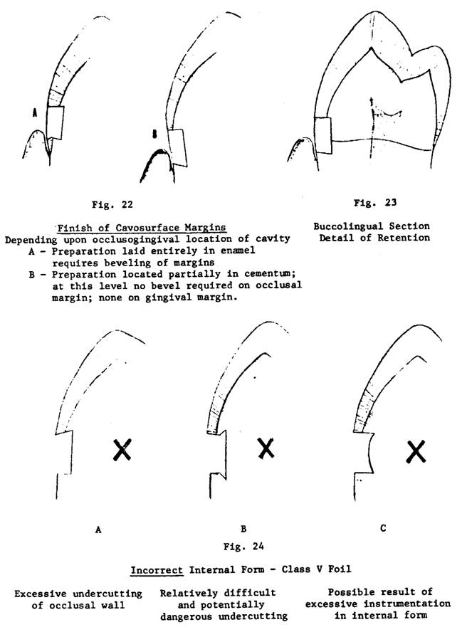
3. Gingival Wall
a.
Undercut.
b. Meets the axial wall at a
definite acute angle (Fig. 23).
4. Occlusal
wall is perpendicular to the cavosurface of the tooth
or very slightly undercut to meet the axial wall at a right angle or very
slight acute angle (Fig. 23)
5. Retention, therefore, is
gained principally by the convergence of the gingival and occlusal
walls, and to a lesser degree by the box effect of the slightly divergent
proximal walls. Excessive retentive features are not essential, for this
restoration is not subjected to external forces.
6. The internal portion of
the preparation is finished with definite straight line angles and with sharp
point angles. Great care must be observed to avoid the overoperating
of these line angles and the attendant dangerous consequences (Fig. 24).
CONVENIENCE FORM
Convenience form is not a
factor for this class of foil cavity, for it is readily accessible to
instrumentation.
Clinically, access is
achieved by retracting the gingival tissue by suitable means so as to present a
proper field and to have the area readily available for instrumentation.
FINISH OF THE ENAMEL WALLS
1. Enamel walls are planed
smooth and straight with a freshly sharpened cutting instrument.
2. The location of the walls
and the condition of the enamel determines whether or not any or all of the cavosurface margins should be beveled and to what extent
(Fig. 22).
3. All walls are finished so
that the margins are straight and true and devoid of any fragile or loose rods.
4. Gingival Wall
a.
If established in enamel, - the cavosurface margin
will be slightly beveled in keeping with the plane of the enamel rods in that
area. In this instance, the cavosurface bevel will be
parallel with the plane of the enamel rods (Fig. 22-A).
b.
If in the cementum of the tooth, - a truing and
planning of the margin will automatically establish the required cavosurface angle (Fig. 22-B).
USUAL SEQUENCE OF INSTRUMENTS
33½ inverted cone bur
10-4-8
hoe
6 1/2-2 1/2- 9 hoe
15-15-3 Wedelstaedt
chisel, regular bevel
15-15-3 Wedelstaedt
chisel, reverse bevel
Medium angle formers, Right
and Left
CLASS 5 FOIL
CAVITY PREPARATION
Instruments
#212 gingival retractor,
stabilized
Inverted cone bur, 33 1/2,
steel, h.p., new
Hoe, 10-4-8 (A-21)
Hoe, 6 1/2- 2 1/2- 9 (A-23)
Angle formers, medium or
small, (A-36 & 37, or 38 & 39)
Wedelstaedt chisels, 15 or 11½ width,
regular and reverse bevel (A-3 & 4, or 5 & 6)
Right angle explorer (G-3)
Preparation
1. Inverted cone bur - 33½ -
in straight handpiece to
rough out
the preparation
remove
central stock
establish
proximal walls - with end of bur
establish
gingival wall - with end of bur
establish
incisal wall - with side of bur (with end directed
toward proximal surface).
2. 10-4-8 hoe - to smooth and define
axial
wall
proximal
and incisal walls, line angles and point angles.
3. 23 hoe (6½-2½-9)
establish
gingival wall
accentuate
axio-gingival angle
4. Angle formers may be used,
with caution, to sharpen internal line and point angles.
5. Wedelstaedt
chisel, reverse bevel to plane and true enamel walls.
6. Wedelstaedt
chisel, regular bevel to plane axial wall.
7. G-3 explorer to test and
clean line and point angles.
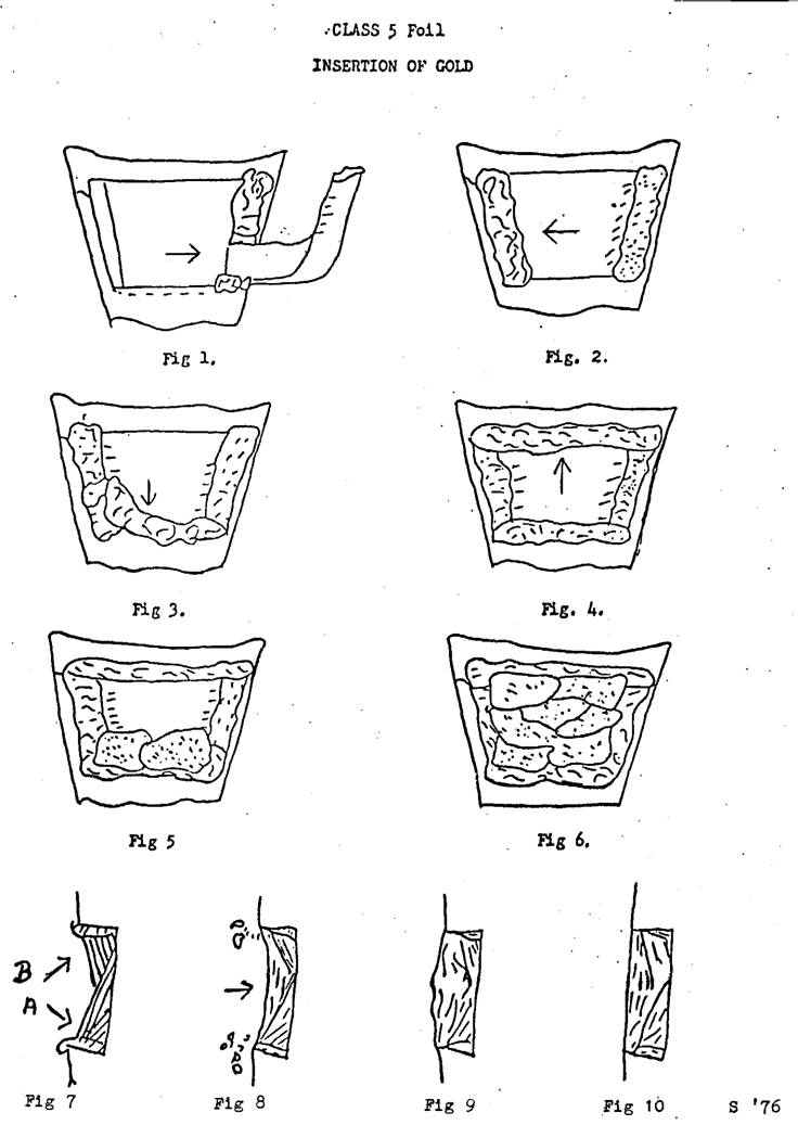
INSERTION OF FOIL
Instruments
Number Name Formula
U.W. - 49 Foil pliers
B-14 Parallelogram, hoe 5.5 x 12 - 5.5 - 12
B-15 Parallelogram, hatchet 12 x 5.5 - 5.5 - 12
B-12 Passer 0
- 11 - 10
B-1 or 21 Round face, straight 5.5 or
B-3 or 23 Round face, monangle 5 - 4.5 - 7
B-8 or 28 Foot condenser 10 x 7.5 - 10 - 13
1. Line one proximal wall
with noncohesive foil (Fig. 1) using foil pliers and
parallelogram condenser. Select a pellet of such size that it is somewhat
longer than the length of the wall and slightly wider than the depth of the
wall. Form it into an elongated cube, between thumb and finger and the beaks of
the pliers. Carry foil to place on one proximal wall with pliers; stabilize
with one parallelogram condenser. Exchange pliers for second parallelogram;
flatten foil to wall (don't overwork it).
2. Repeat step 1 and line the
other proximal wall, then the gingival, then the incisal
with one noncohesive pellet on each. (Fig. 2, 3, 4)
3. Stabilize noncohesive foil and begin insertion of cohesive foil (Fig.
5). And with the parallelogram condensers place 2 or 3 annealed pellets in
floor of preparation, using a size such that the 2 or 3 will cover the axial
wall and contact the noncohesive foil. Stabilize noncohesive with one parallelogram; hand condense cohesive
with other parallelogram.
4. Build up cohesive foil,
gingival portion (Fig. 6) with the 5.5 condenser. The line of force is into axio-gingival
angle. (Fig. 7-A) Build up some bulk of foil in gingival half of cavity.
5. Lock into incisal with 5.5 condenser. Change line of force from
gingival to incisal direction; stabilize gingival
portion with parallelogram. (Fig. 7-B) Some force is directed toward proximal
walls.
6. Build up cohesive foil
with 5.5 straight condenser and 5.0 monangle. Compact the foil against surrounding walls,
keeping central portion under-contoured (saucer effect). Ensure sound
compaction of cohesive foil into angles (especially proximo-occlusal
angles) with smaller condenser (5.0 or 4.0 monangle).
Step condenser in orderly fashion in rows, back and forth from central area
toward margins.
7. Pinch off noncohesive foil (Fig. 8). As margins are approached, scuff
off excessive noncohesive foil, especially in angles
formed by surrounding walls. Make final marginal coverage with cohesive foil.
Scuff off excess of each pellet so cavosurface margin
is not lost to view.
8. Complete contour using the
same condenser. Force is perpendicular to axial wall (Fig. 8), and build to
slight overcontour (Fig. 9). Check complete marginal coverage with G-3
explorer.
9. After condensing. Confirm
compaction with foot condenser.
FINISHING
Instruments
Straight burnisher
(F-2)
Shooshan files, pull-cut and push-cut
(B-41/42, 44/45)
Small gold knife (B-51)
Discs - 3/8" - garnet 4/0,
cuttle 1/0, 2/0 & 3/0
Miniature
disc mandrel, h.p.
Vaseline
Snap-on rubber cup in
mandrel, h.p.
Lap emery, 303
White polishing compound 309W
Transilluminator
1. Verify compaction by
burnishing surface with straight burnisher.
2. Reduce excess foil using
push-cut files on proximal and gingival margins and central portion. Use
pull-cut file on incisal portion. Good finger rests
essential to avoid bruising tissues under dam, with files etc.
3. Establish correct contour.
Alternate between files and discs and gold knife. Using discs, progress from coarsest to
finest; lubricate foil and rubber dam lightly with vaseline. Run disc at slowest speed; keep it moving
to avoid losing contour.
4. Check for marginal
flashing using gold knife with push-cut, use the back of knife. Trim exactly to
margin. (Fig. 10)
5. Exercise extreme care
against scarifying cementum.
6. Polish. Keep tooth cool
with air blasts continuously. Lap emery, dry, on rubber cup, slow speed; light
intermittent contact. 309W - dry, on rubber cup, high speed, very light
contact.
7. Clean field. Remove debris
with right angled explorer and light blasts of air. Transilluminate
after dam and retractor removed.
8. Irrigate and
massage soft tissues.
The above lists,
instructional materials & recommended readings have been prepared by Dr
Gerald D Stibbs and the members of the George Ellsperman Gold Foil Seminar. They have been used be the George Ellsperman Gold Foil Seminar for our instructional manual
and course materials over the years.
Some modifications have been made from the original list by the members
of the GEGFS, but they are largely the work of Dr Gerald D Stibbs.
The Digital
edition has been the work of the George Ellsperman
Gold Foil Seminar under the direction of Dr. Bruce B Smith.