RUBBERDAM
The use of a rubber dam to
obtain a proper operating field for direct gold restorations is imperative. The
acquisition of a standardized technique eliminates the problems of excessive
time for placement of the dam and of patient objection. With such a technique,
a dam can be placed easily in an average time of two to three minutes,
including the placing and stabilizing of any necessary retractors or
separators. The time between the administration of the local anesthetic and
the onset of effective anesthesia can be utilized by placing a dam and securing
an optimum operating field.
Set out -
On Operating Tray- Mirror
Explorer
Cotton pliers
Small T-burnisher
Littauer suture scissors
On Assistant's Tray- Rubber dam 5”x 6" or 6”x 6"
(washed and powdered)
Rubber dam punch
Dam lubricant (small tube of lather shaving cream)
Protective cream for patient's lips
Retainer holder
Required retainer & retractor
Rubber dam weights
For gingival retractor or separator‑
Red compound stick
Glass of hot water
Flame
On Headrest Lever- Wizard rubber dam holder (top toward
patient)
On Patient's Left Shoulder- Rubber dam pad (top toward patient)
On Patient's Right Shoulder- Length of dental floss
APPLICATION
Sequence of Procedure
1. Assuming patient has recently
received a prophylaxis, and that teeth are definitely free of calculus, plaque
and stain, operator irrigates mouth with comfortably warmed mouthwash to
thoroughly remove any superficial debris.
2. Operator receives floss
from assistant to pass through contact points, noting degree of contact, and
sharp edges which should be removed with steel strip.
3. Assistant, meanwhile, sets
out on assistant's tray or table the rubber dam, dam punch, required retainer,
retainer holder, soap, face pad and dam holder.
4. Punch necessary holes,
usually 3.5 mm of rubber between holes.
5. Assistant applies
protective cream, such as Lanoline, on patient's lips. (Just
a thin film).
6. Hold dam, tissue side up,
for assistant to apply lubricant to the punched section.
7. Place retainer in dam, if
operating on posterior teeth.
8. Assistant passes retainer
holder and steps to left side of chair.
9. Operator places retainer
on tooth, assistant takes retainer holder, and operator slips dam over jaws of
retainer and edge-ways through as many contacts as readily possible, assistant
holding loose ends of dam out of the way.
10. Place face pad.
11. Assistant hands dam
holder to operator, opens folds of dam and holds edges of right side taut for
operator to attach holder. (Upper clip is attached to uppermost corner of dam.)
Operator passes holder around patient's head while assistant draws left side of
dam taut for attachment to holder. Holder is drawn tight. Have elastic of
holder at such a level on the back of the head (at or slightly above the
lambda) that when tightened the holder will not tend to slip up or down, but
remain steady.
12. Assistant stretches septa
of dam over contacts strongly but without discomfort to the patient, using
-"left side front" position for upper anteriors
and all lowers, "left side behind" position for upper posteriors
-while operator eases rubber through contacts with floss.
13. Place moistened saliva
ejector of proper loop size for the mouth, through small slit cut in suitable
location in the dam, so it will offer the least possible obstruction in the
field of operation.
14. Seal is completed by
averting the edge of the dam around each tooth with floss in the interproximal areas and with small burnisher
on labial and lingual, while assistant dries teeth thoroughly with compressed
air. The drying of the teeth is most important at this phase. NOTE: It is not
necessary or advisable to ligate the teeth.
15. Any folds in the dam are
eliminated by catching tucks in lower clip of holder, and if necessary a weight
is placed by assistant.
16. Immediately apply coating
of varnish (not vaseline)
over all exposed silicate cements and porcelain inlay margins.
17. If gingival retractor is
to be used, first remove molar or bicuspid retainer if possible, then place the
gingival retractor and stabilize it with compound.
18. Proper field now presents
and operation may proceed.
REMOVAL OF DAM
Sequence of Procedure
1. If chair is tipped back or
if headrest is at other than a normal setting, reestablish normal operating
position, advising patient of your intention to do so prior to actually doing
it.
2. With water syringe and
evacuator irrigate and rinse the field. With air syringe, blow out any
remaining debris, and also blow loose debris off patient's drape so it will not
fall on to clothing.
3. Have warm mouthwash ready.
If equipment includes spray bottle connection, connect it.
4. Remove separator or
gingival retractor (only), and rubber dam weights, if any.
5. Remove saliva ejector.
6. Carefully stretch dam labially or buccally and occlusally to lift rubber septa free of interproximal
tissues.
7. Out septal
rubber, usually from buccal, with sharp ligature
scissors or curved crown scissors held parallel with occlusal
plane, being extremely cautious not to cut gingival tissues, lips, cheeks or
tongue. Draw the cut portions of rubber to the lingual until free of the interproximal surfaces.
8. Then, and only then,
remove the routine retainer if one is present. Hand it and retainer holder to
assistant or place it on side table. Do not place it on operating tray.
9. While supporting dam in
position with the right hand, unfasten dam holder from both sides, using left
hand. Place holder on side table.
10. If necessary, caution
patient against biting the teeth together.
11. Carefully gather dam and
pad toward the mouth area and into the right hand, at the same time wiping
patient's face with the dry portion of the pad.
12. Flush mouth with warm
mouthwash. Direct the spray first against the back of the retracting mouth
mirror, then gradually bring it over to the site of
the operation. Use enough solution so the patient has a reasonable quantity
with which to irrigate the mouth.
13. Before discarding the
dam, examine it to be sure that all of the rubber has been removed.
14. Carefully examine teeth
and interproximal areas to be doubly sure that none
of the dam still remains.
15. Loosen any remaining
compound, carving trimmings, etc. from teeth and flush out all particles,
repeating use of mouthwash as many times as may be necessary to remove all
debris. Check with transillumination, especially
under the free gingival tissue of the tooth operated on.
16. Treat any areas where
retainer, retractor or separator has impinged on the tissues, by gentle massage
with clean fingers and by the application of a mild antiseptic, such as Campho-phenique.
17. Irrigate patient's mouth
again with mouthwash; be sure the mouth is comfortable, and the face free of
debris.
18. Patient now is offered a
hand mirror and shown the work which has been done, with whatever explanation
and education is desired. Instruction in home care is given if necessary.
19. Chair is lowered and
patient is dismissed.
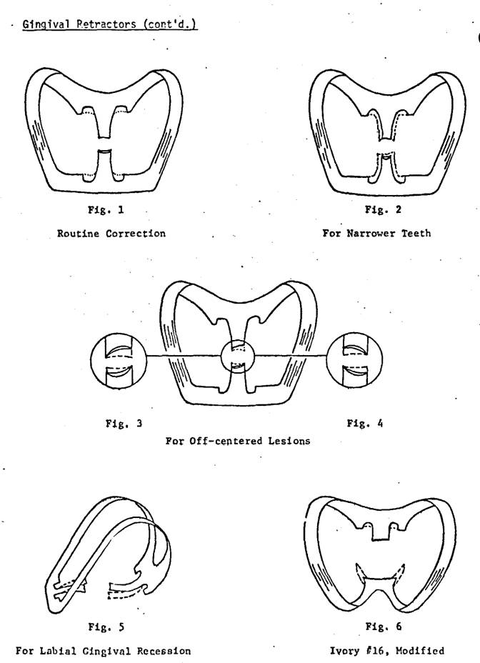
GINGIVAL RUBBER DAM
RETRACTORS
SELECTION
Ferrier #212 Retractor
A minimum of 3 is required,
with 2 being modified as described below. Three additional ones are a definite
advantage (Figs. 1 - 5).
Ivory #16 Retractor
Useful for gingival cavities
in molars, but only after the bulk of the buccal jaw
is reduced markedly, and its shape modified carefully, to fit the contour of
the tooth (Fig. 6).
ADVANTAGES
A properly designed and
placed gingival retractor
1.
Provides proper visibility and access for gingival cavities, shoulders for
porcelain veneer crowns, etc.
2.
Retracts and protects gingival tissues.
3.
When stabilized with compound, it also:
a.
Distributes operating force over several teeth
b. Provides finger rest
c. Prevents retractor from rocking on tooth root, thus
avoiding damage of cementum and supporting tissues by
retractor jaw.
FERRIER #212
RETRACTOR
This retractor or clamp,
designed by W.I. Ferrier, is the best one for most gingival third restorations,
from the standpoint of providing a clear operating field, with minimal
impingement upon the supporting tissues or damage to the tooth surface. It is excellent
also for crown preparations on anteriors and
bicuspids.
To achieve maximum results
with it, the principles and technique for its use must be understood and
followed. The #212 retractor is designed so that, when positioned properly, it
will closely approximate the labial supporting tissues and provide an optimal
operating field. However, in so doing, it is an unbalanced instrument; that is,
if it is placed on a tooth and not supported or stabilized, it will tilt so the
lingual jaw slides gingivally against the lingual
tissues and the labial jaw lies in a more horizontal plane thus reducing
access to the area to be operated upon. Therefore, whenever this retractor is
placed on a tooth, it must always be locked to position or stabilized with
modeling compound, or the supporting tissues and cementum
will be damaged. It is important that during the interval between positioning
and stabilizing the retractor, it must be supported by a finger with pressure
directed occlusally, or the lingual jaw will creep gingivally and the access to the lesion will not be as good
as it could be.
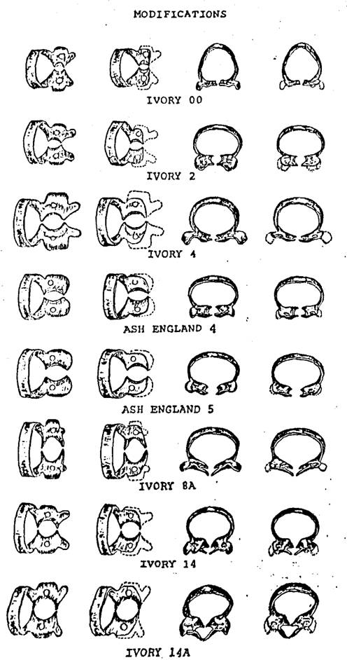
MODIFICATIONS
1. The basic form of this
retractor is such that, without modification, it will fit the great majority of
teeth. Usually, however, some finishing must be done with each of the
instruments as received from the manufacturer. The labial and lingual notches
for the beaks of the clamp holder should be accentuated to ensure a positive
grip (Fig. 1). It is also important that the edges of the end of each jaw
should be smooth, polished and slightly rounded, so it will not scarify the
tooth surface. The preferred finish for the carbon steel retractor is nickle plating rather than chrome, and satin rather than
high polish. Compound does not adhere to a chromed surface as well as to a nickled one. If the retractor is made of stainless steel
this can not be controlled. The reflections from a highly polished metal
surface are annoying to an operator's eye. If a clamp is highly polished, it is
improved by dulling the surface by sandblasting.
2. For teeth with lesser mesiodistal dimension, and more rounded labial and lingual
root contours, such as lower incisors, lower first bicuspids and some upper
laterals, one retractor is modified by narrowing the labial and lingual jaws
slightly, and by increasing the concavity of their edges (Fig. 2). The ground
edges are thinned somewhat, then smoothed, rounded and polished before use.
3. For teeth with marked
recession of the labial tissue, the lingual jaw of the retractor is bent more incisally and the labial jaw is bent a little further gingivally (Fig. 5). This is not an easy modification
however, for if not performed properly much of the original advantage of
optimal operating field access is lost. The more the labial jaw is bent, the less
is the access to the operation.
If
the retractor is of stainless steel,
bending is accomplished by holding the retractor near the lingual jaw with a
pair of flat nosed pliers (e.g. #104); heat the lingual jaw in a high heat
blowtorch flame until cherry red; quickly grasp the heated jaw with a pair of
fine nosed pliers (e.g. #136) and carefully, but quickly, bend it occlusally to the desired extent (approximately 1 - 1.5
mm). Repeat the same procedure to modify the angle of the labial jaw; minimize
the arc of the curve of the jaw; this is the difficult part. Bench cool the
retractor (don't quench); then place retractor in a cool inlay burnout furnace
and raise the heat to 500°F remove the retractor and quench in water.
If
the retractor is of carbon
steel, heat and bend the jaws, in the same manner as above, but as
soon as bending is accomplished. Bench cool.
Repolish
the surface with a Burlew disc.
4. To minimize loss of chair
time, it is advisable to have two other retractors modified for teeth in which
the lesion to be operated is off-centered mesiodistally.
The alteration consists of grinding a bit of the left side of the edge of the
labial jaw and the right side of the lingual jaw of one retractor (Fig. 3), and
the opposite sides of the labial and lingual jaws of the other retractor (Fig.
4).
5. Another modification is
that of annealing a retractor so it can be bent to fit any unusual case that
presents. This is done by heating a retractor in a furnace to 1300°F. and then turning off the furnace to cool slowly. The
instrument may then be bent at will for the case at hand.
APPLICATION
1. Preparatory set-up
consists of
gingival
retractor
clamp
holder
F-3 burnisher (T-shape)
bunsen
glass of
hot water
stick of
red compound
compressed
air
2. For any degree of
efficiency, it is necessary to have an assistant for this procedure. If a chairside assistant is not available then the patient's
help should be elicited with essential briefing.
3. Until the operator is
experienced, a gingival retractor is selected and carried gently to the tooth
with the clamp holder, to test it for fit. If it does not fit, one of the
modified retractors is tried. Further modification is sometimes necessary. The
retractor is then set aside in readiness.
4. The dam is placed; then
previously placed posterior clamps usually may be removed.
5. The gingival retractor is
carried to the tooth with the clamp holder.
6. The lingual jaw is
positioned first, as follows: It should
be just gingival to the cingulum or lingual height of
contour, so it will not slip incisally; it is usually
carried to the level of the lingual soft tissue (if normal), but in no case is
it set on the tissue, or on the dam. It is strongly supported in this position
with the index finger, exerting pressure incisally
and labially so the retractor will not slide further gingivally. This support must be maintained without
interruption until the instrument is stabilized with compound.
7. With the dam retracted
from the labiogingival area, the labial jaw is placed
and carried gingivally very carefully, so as to
retract the gingival tissue without tearing it.
Retraction should be sufficient so an adequate amount of root surface is
exposed gingivally to the anticipated gingival
extension of the proposed cavity. 1mm is desired.
8. Usually the desired amount
of retraction cannot be obtained this way without damaging the gingival tissue;
therefore, the clamp holder is laid aside while the retractor is still
supported constantly from the lingual, as described above; then with the ‘T’ burnisher in the other hand, the labial notch is engaged
and the labial jaw is gradually retracted further, by degrees. With this
“delayed “ retraction the gingival tissue will stretch
without tearing.
9. The plane of the bows of
the retractor should parallel the occlusal plane of
the teeth. The labial jaw should rest
snugly against the labial soft tissue.
10. The retractor is
stabilized with red compound, always.
a. Assistant softens about 3/8” of the end of a stick of
red tracing compound by rolling it between the fingers over a flame until the
compound begins to droop (be careful not to overheat, or the compound will drip
on the patient or instrument tray); then temper it in a glass of hot water for
about 5 seconds; then hand it to the operator who, after dipping his fingers in
the water, twists off the required amount of soft compound (as little as will
do the job). Note: With gloves on a
little Vaseline helps to stop it from sticking to the gloves. Too much will inhibit
sticking to the tooth. Painting the dry
teeth with varnish also helps with adherence.
b. Operator molds compound to somewhat pyramidal shape,
touches the tip against the patient bib to dry the surface, then holds tip over
the flame.
c. Seared compound is applied
under the bow of the retractor, introducing from the side of the bow furthest
from the tooth to be operated as possible.
Thee freshly heated surface of the compound is touched to the retractor
and to the tooth to be sure it sticks.
It is then molded to fill the space between thee bow and the teeth, and
the interproximal spaces.
d. Assistant chills compound with compressed air.
Operator guides the air tip while assistant heats more compound
to be similarly placed under the other bow of the retractor.
e. Remember that at the conclusion of the operation, the
retractor must be removed. This is
facilitated if compound is not permitted to block the notches for the beaks of
the clamp holder.
11. Be sure lip is not
pinched under bow of the retractor, and that lingual jaw is not impinging on
the dam.
12. A good field should now
exist. The retractor should be firmly secure and should be usable as a definite
finger rest.
13. When the operation is
completed, the retractor and compound can usually be removed in one mass by
carefully engaging the retractor with the clamp holder. Be sure the grip is
sure. Gently stretch the retractor and lift it and the compound off, being
careful not to mar the surface of the tooth or the restoration. Remove any
traces of compound.
14. Remove the dam as usual;
check the gingival crevice with an explorer, air and transillumination
for complete removal of any debris. Gently massage the soft tissues and
irrigate with warm mouthwash. An application of medication such as Campho-phenique is usually desirable.
15. If the retractor has been
placed properly and if the instrumentation has been expeditious, the gingival
tissues should not be torn or mutilated. The aim should be to conclude the
sitting with no hemorrhage of the tissues and only an indentation from the jaw
of the retractor on the unbroken soft tissues.
USE OF FERRIER-TYPE SEPARATOR
USES
1. Produce slight separation
of teeth.
2. Stabilize small or mobile
teeth during operative procedures.
3. Retract dam and interproximal gingival tissues.
4. Distribute operating force
to more than one tooth.
5. Provide finger rest.
APPLICATION
1. Select proper instrument
for case. In general
#1 -
most anteriors
#2 -
long anteriors, or in cases of gingival recession
#3 -
between cuspid and first bicuspid
#4 -
between bicuspids
#5 -
between bicuspid and molar
#6 -
between molars
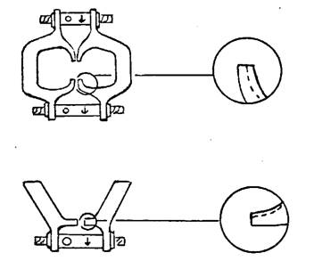
2. Jaws of separator may need
to be thinned and sometimes require modification by grinding. When this is
done, smooth and polish the ground surface before applying to tooth.
3. Be
sure both adjustment screws work loosely. This property of "shake" is
most important. If they are stiff, it is recommended that the instrument be
returned to the manufacturer for correction. In an emergency, however, a paste
of 303 and glycerin may be applied to the threads, and the screw worked back
and forth until the necessary clearance is established, then scrub the threads
clean, and dry.
4. Place the separator.
a. #1, 2
and 3 have adjustment screws of unequal length. The separator is designed for
the longer one to be applied to the labial.
b.
Open the jaws enough so they will engage the teeth and not pinch the dam
between separator and tooth..
c. Steady
the instrument in proper position until it is stabilized with compound.
d.
The plane of the bows should parallel the occlusal
plane of the teeth.
5. Stabilize with compound.
a.
It is preferable to have assistance at this stage rather than work alone.
b.
Assistant softens about 3/8" of the end of a stick of red tracing compound
over gas or alcohol flame until the compound begins to droop; then tempers it
in glass of hot water for about 5 seconds; then hands it to operator who, after
dipping his fingers in the water, twists off the required amount of soft
compound (as little as will do the job).
c.
Operator molds compound to somewhat pyramidal shape, touches tip against
patient bib to remove water, then holds tip over flame.
d.
Seared compound is applied under bow of separator, touching some of the freshly
heated surface to both separator and teeth. If possible, it is introduced from
the side of the bow furthest from the operation, so the field will be neater.
It is molded to fill the space between the bow and the teeth, and the interproximal areas, and smoothed.
e.
Assistant chills compound with compressed air, operator guides the air tip
while assistant heats more compound to be similarly placed under the other bow
of the separator.
6. The adjustment screws are
carefully tightened with the wrench.
a.
Arrow indicates direction for tightening.
b.
Separation is achieved gradually, a quarter turn at a time, alternating between
labial and lingual. Because of the spring in the bows, separating action
continues after screws are adjusted.
c. Be aware constantly of the degree of separation, and
ease it as much and as soon as possible.
d.
Separation, excessive either in degree or duration, will
damage the supporting tissues and will result in prolonged discomfort
for the patient.
7. When removing separator,
release tension of screws gradually, first one, then the other. If done
rapidly, it will be painful. Be sure all compound is removed from the teeth.
8. Before sterilizing the
separator be sure to remove all compound, and scrub
points of jaws with soap and brush.
The above lists,
instructional materials & recommended readings have been prepared by Dr
Gerald D Stibbs and the members of the George Ellsperman Gold Foil Seminar. They have been used be the George Ellsperman Gold Foil Seminar for our instructional manual
and course materials over the years.
Some modifications have been made from the original list by the members
of the GEGFS, but they are largely the work of Dr Gerald D Stibbs.
The Digital
edition has been the work of the George Ellsperman
Gold Foil Seminar under the direction of Dr. Bruce B Smith.